AP Physics C Energy Lab
The purpose of this investigation is to verify the concept of conservation of energy and explore the nature of potential energy. A lab cart on a track will be attached to a pivoting spring. The horizontal component of the spring’s force will be measured by a wireless force sensor while the position, velocity, and acceleration are measured with a motion detector.
Procedure
Adjust the cart's track so that it is level. Attach a GoDirect Force and Acceleration sensor to the top of the lab cart. Use a ring stand and clamp (not shown) to anchor and suspend a spring directly above the cart. Use a short section of stiff wire to attach the free end of the spring to the force sensor hook. With the cart at rest, adjust the position and height of the spring so that it is pulling (very slightly) vertically straight up on the hook. The cart should now oscillate back and forth with the spring pivoting on its anchor as shown below:
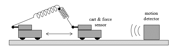 |
There should be only one unique equilibrium position at which the cart will sit at rest on the track (with the spring only slightly stretched).
1. Run Graphical Analysis and connect the sensors for data collection – preferably by Bluetooth so that the cart can move freely.
2. Situate the cart at its equilibrium position and then zero both sensors – force and position should both indicate zero when the cart is at rest.
3. Collect data with the cart oscillating back and forth – try to maximize the distance the cart is moving, being careful not to damage any equipment or exceed the limits of the sensors. The data should not show the cart at rest or being pushed – only the spring should be affecting the cart for the entire time of data collection. Repeat if necessary to get a set of data showing smooth oscillations.
4. Disconnect the spring and move it out of the way. Collect additional data showing the motion of the cart coasting on the track under the sole influence of friction. Repeat with the cart coasting in the opposite direction.
5. Use a triple beam balance to determine the total mass of the cart with the force sensor still attached.
6. Share the data with each member of your lab group. Everything in the analyses section can and should be completed individually.
Analyses
Spring Force Component:
1. Create a high quality, well labeled graph of Force vs. Position for the cart oscillating. This graph shows how the horizontal force component of the spring acting on the cart varies with respect to the cart’s position on the x-axis.
2. Use the Apply Curve Fit command to determine an appropriate polynomial equation to best model the data. One option that should closely match the data is an equation of the form y = ax3 + bx. If this does not give a satisfactory close match, then it may be necessary to use additional terms in the polynomial, or do further trials to get better data.
3. Use the Export command or a screenshot to save the graph so that it can be printed to include with your report.
Friction:
1. Create a high quality, well labeled graph of Velocity vs. Time with the cart coasting when disconnected from the spring. Include both trials so that the one graph shows the cart’s velocity when moving in both directions.
2. Use the Apply Curve Fit command to determine two linear regressions showing the effect of friction with the cart moving in each direction.
3. Use the Export command or a screenshot to save the graph so that it can be printed to include with your report.
Energy:
1. In the Data Table, under the Column Options menu, choose Add Calculated Column and create a column of kinetic energy. Enter the Name (K), Units (J), and an appropriate equation.
2. In a similar way create a column of potential energy. Enter the Name (U), Units (J), and an appropriate equation. It is up to you to determine this equation! Use the curve fit from Force vs. Position to derive an equation for calculating potential energy. The reference point for this function should be the origin. In other words, the potential energy calculated is relative to the position x = 0, which is also the position at which the force of the spring F = 0.
3. Also create a column with the total mechanical energy E. This is the sum of the kinetic and potential energy of the system.
4. OPTIONAL: If you wish to do so, it is possible to add additional columns to “account for” the energy lost due to friction. Create a column that gives the total distance traveled by the cart (integrate the speed (not velocity) of the cart). Then use the results of the friction experiment to determine the average force of friction and create a column showing the work done by friction. Finally, create a column showing E + heat (or E – Wf). This is based on the assumption that the work done by friction converts mechanical energy almost entirely into heat.
5. Create a high quality, well labeled graph of Energy vs. Time for the oscillating cart and plot all three values K, U, and E. (Or if you created the optional column, plot K, U, and E – Wf.) The three plots shown should be readily distinguishable by symbols, colors, legend etc. This graph will not have any equations or curve fits. On this graph it is best to “connect the dots” with line segments so that it is easier to follow the trends.
6. Use the Export command or a screenshot to save the graph so that it can be printed to include with your report.
7. Create a high quality, well labeled graph of Energy vs. Position for the oscillating cart and plot all three values K, U, and E. (Or if you created the optional column, plot K, U, and E – Wf.) The three plots shown should be readily distinguishable by symbols, colors, legend etc. This graph will not have any equations or curve fits. On this graph it is best to “connect the dots” with line segments so that it is easier to follow the trends.
8. Use the Export command or a screenshot to save the graph so that it can be printed to include with your report.
9. Create a high quality, well labeled graph of Energy vs. Time showing only total mechanical energy E. Use the Apply Curve Fit command to determine a linear regression. Whenever including a line or curve of best fit it is best to not use connecting line segments between data points.
10. Use the Export command or a screenshot to save the graph so that it can be printed to include with your report.
11. Create a high quality, well labeled graph of Energy vs. Distance showing only total mechanical energy E. (Note: if you have not already done so you must create a column of distance traveled by the cart (integrate the speed (not velocity) of the cart).). Use the Apply Curve Fit command to determine a linear regression. Whenever including a line or curve of best fit it is best to not use connecting line segments between data points.
12. Use the Export command or a screenshot to save the graph so that it can be printed to include with your report.
Questions
1. Referring specifically to the graphs, data, and analyses state whether (or not) the experiment supports the concepts of conservation of energy, work, etc. and explain how so.
2. Starting with the curve fit equation that gives the horizontal spring force component as a function of position, derive the potential energy function that was used to create the graphs. Show all work.
3. Using the two linear regressions on the velocity vs. time graph, and the mass of the object, determine the best value for the amount of friction. Show all work.
4. The
amount of friction relates to the linear regressions on the graphs E vs.
t and E vs. d.
(a) Use the E vs. d graph and equation to determine the amount of
friction and determine the percent difference from that found using the
velocity graph.
(b) Use the E vs. t graph and equation, and the previously determined
amount of friction, to determine the average speed. Also determine the the
average speed by simply dividing the total distance by the total time. Then
determine the percent difference in these two values.
5. Write an intelligent, grammatically correct paragraph or two discussing both the signs of error and the likely sources thereof.
A complete report (50 pts): (pages in this order)
q Velocity vs. Time graph (cart coasting both directions, two linear regressions) (4)
q Force vs. Position graph (with polynomial regression equation) (4)
q Energy vs. Time graph (showing K, U, and E or E – Wf, no curve fits) (8)
q Energy vs. Time graph (E only, with linear regression) (8)
q Energy vs. Position graph, (showing K, U, and E or E – Wf, no curve fits) (8)
q Energy vs. Distance graph (E only, with linear regression) (8)
q On separate paper, responses to the questions. (10)