AP Physics C Assignment - Capacitance
Reading Chapter 26 and pp. 814 - 818
Objectives/HW
|
|
The student will be able to: |
HW: |
|
1 |
Define and calculate capacitance in terms of voltage and charge and solve related problems. |
1 - 5 |
|
2 |
Solve steady-state problems involving series and parallel connections of capacitors and batteries. |
6 - 8 |
|
3 |
Solve problems relating capacitance to geometry and dielectrics for parallel plate, cylindrical, and spherical capacitors. |
9 - 19 |
|
4 |
Analyze RC circuits in terms of the appropriate differential equation and resulting exponential functions for charge, current, voltage, etc. |
20 - 24 |
Homework Problems
1. A capacitor of 4700 μF is connected to a 3.00 V battery. (a) What total amount of charge will be stored in the capacitor? The battery is then disconnected and replaced with a 1.2 kΩ resistor. (b) What is the initial current in the resistor? (c) What will be the total heat generated in the resistor as the capacitor completely discharges?
2. In a certain defibrillator a capacitor stores electric energy in amount 160 J. The capacitor then totally discharges 0.18 C as the shock is delivered to the patient. (a) Find the required capacitance. (b) Determine the initial current if the patient's chest has resistance 65 Ω. (c) Determine the charge and energy remaining when the current has dropped to 10.0 A.
3. A typical rechargeable battery supplies a voltage of 1.50 V and has a capacity of 450 mAh. (a) What capacitance would be required to store the same amount of energy at 1.50 V? (b) Could such a capacitor take on the role of a battery in an electrical device? Explain.
4. A 3.0 volt battery is used to charge a 0.10 millifarad capacitor. The internal resistance of the battery is 2.0 ohms. (a) Determine the voltage of the capacitor and the current in the circuit when the charge stored reaches amount 0.20 mC. (b) Make a table of values showing the voltage of the capacitor and the current in the circuit as the amount of charge stored climbs through amounts 0, 0.10 mC, 0.20 mC, and 0.30 mC. (c) Consider the amount of time for the charge amount to increase by increment 0.10 mC as the capacitor is charging - does this value increase, decrease, or remain constant? Explain.
5. Charge of amount Q is stored in a capacitor of capacitance C and then connected to a resistance R. (a) Derive an expression for the current in terms of Q, R, and C. (b) Sketch a current vs. time graph and estimate the time for the charge to drop to Q/2 by using a trapezoidal area. (c) Use the result to estimate the charge remaining after a time of 4RC.
6. Two capacitors C1 = 30.0 μF and C2 = 60.0 μF, are connected to a 12.0 V battery. Determine the voltage and amount of charge for each capacitor if the type of connection is: (a) series and (b) parallel. (c) Determine the effective total capacitance in each case.
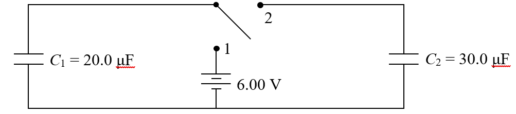
7.
Two
capacitors are connected to a 6.00 V battery and a single-pole double-throw
switch (SPDT) as illustrated below. The switch is in position 1 for a long
while and then it is moved to position 2 and left there. Capacitor C2
is initially uncharged. (a) Determine the eventual charge and voltage of each
capacitor after the switch is in position 2. (b) Find the amount of charge
that flows through the switch after it makes contact at position 2.
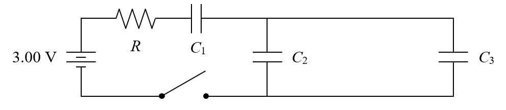
8.
Examine
the circuit below with capacitors: C1 = 10.0 μF, C2
= 10.0 μF, and C3 = 40.0 μF and resistor R =
5.00 Ω. All the
capacitors are initially uncharged as the switch is closed. (a) Determine the
initial current in each capacitor when the switch is closed. After the switch
has been closed for a long time, determine the following: (b) the voltage
across C1, (c) the charge on C2, and (d)
the energy stored in C3.
9. A capacitor is formed by placing two circular metal plates of radius 20.0 cm parallel to one another and separated by 0.500 mm of air. (a) Find the capacitance of this configuration. (b) If connected to a 5.50 V battery how much charge develops on each plate? (c) An electric field of 3.0 x 10⁶ V/m between the plates would lead to a spark - based on this, what is the maximum energy that could be stored?
10. Suppose it is desired to form a capacitance of 10.0 μF using the same basic configuration as in the previous problem. (a) What separation is required if the same plates are used? (b) What size plates are required if the same separation is used? (Are either of these practical?)
11. A certain capacitor has parallel plates, area 175 cm2 each, that are separated by 0.30 cm. The capacitor is charged by a 12.0 V battery and then it is disconnected. (a) Determine the amount of charge on each plate. (b) Find the work necessary to increase the separation of the plates to 0.50 cm (without discharging the plates).
12. (a) Show by
derivation that the plates of an "ideal" parallel plate capacitor attract each
other with a force given by ![]() . Hint: use the fundamental relationship
between potential energy and force OR use the field of an infinite plane of
charge. (b) How can lack of dependence on plate separation distance be
explained in light of Coulomb's Law?
. Hint: use the fundamental relationship
between potential energy and force OR use the field of an infinite plane of
charge. (b) How can lack of dependence on plate separation distance be
explained in light of Coulomb's Law?
13. A student makes a capacitor with a piece of paper sandwiched between two rectangular pieces of aluminum foil, 20.0 cm x 28.0 cm. The paper is 0.100 mm thick and has a dielectric constant 3.7 and a dielectric strength of 16000 kV/m. (a) Determine the capacitance. (b) What is the maximum voltage and energy storage for this capacitor?
14. A parallel plate capacitor has square plates, area 0.0350 m2 each, separated by 1.20 mm. The capacitor is charged using a 12.0 V battery and then it is disconnected. An insulating slab of thickness 1.20 mm and dielectric constant, κ = 2.1 is then inserted between the plates. (a) Determine each of the following before and after the insertion of the slab: voltage, charge, electric field, potential energy. (b) Ignoring friction, what work is done to insert the slab?
15. Repeat the previous problem but this time the capacitor remains connected to the battery during the insertion of the slab.
16. Determine a formula for the capacitance of a parallel plate capacitor with a dielectric slab that has a thickness exactly half that of the plate separation.
17. A spherical capacitor is formed by an interior metallic sphere of radius 5.00 cm surrounded by a metallic spherical shell of radius 5.10 cm. (a) Determine the capacitance. (b) Find the amount of energy stored if the capacitor is charged to 2.00 nC.
18. (a) Derive an expression for the capacitance of a cylindrical capacitor consisting of a metallic inner cylinder of radius R1 and a metallic outer cylinder of radius R2, each of the same length, L. Assume the length is much greater than the diameter. (b) If a capacitance of 2.0 pF is desired of a cylindrical capacitor of length 10.0 cm, what must be the ratio of R2 to R1?
19. (a) Derive an expression for the capacitance of a single isolated charged sphere. (b) Use the result to determine the capacitance of a Van de Graff generator with a sphere of diameter 25.0 cm. (c) If the charge on this Van de Graff sphere reaches 3.0 μC, what is the voltage and energy associated with this "capacitor"?
20. A 6.0 V battery, a 220 Ω resistor, a 680 μF capacitor (initially uncharged), and a switch (initially open) are all connected in series, forming a loop. At t = 0 the switch is closed. (a) Find the initial current in the loop. (b) Find the charge on the capacitor at t = 0.100 s. (c) At what point in time will the voltage across the resistor equal 5.0 V? (d) What will be the maximum energy stored in the capacitor if the switch remains closed?
21. In the circuit described above the battery is removed after several minutes have passed. Then the loop is completed without the battery so that the capacitor is connected to the resistor. (a) How much time is required to discharge the capacitor by 99% (i.e. it retains only 1% of its original charge)? (b) What is the current at that point?
22. A student connects a charged capacitor to a resistor and measures the voltage across the resistor as the capacitor discharges. She finds that the voltage drops from 6.00 V to 1.00 V in 4.50 s. (a) How much additional time will be required for the voltage to drop from 1.00 V to 0.500 V? (b) If the resistor is 1.2 kΩ, what is the capacitance of the capacitor?
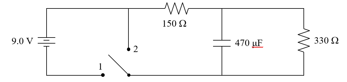
23. The capacitor is
initially uncharged as the switch is moved to position 1 in the diagram below.
(a) Find the initial current through the battery. (b) Find the eventual
current through the battery after the switch has been in position 1 for a long
time. (c) What is the charge on the capacitor at that point? (d) If the
switch is moved to position 2, how much time will it take for the capacitor's
charge to drop by half? (e) Make a careful sketch of current vs. time for the
150 Ω resistor
illustrating the described actions.
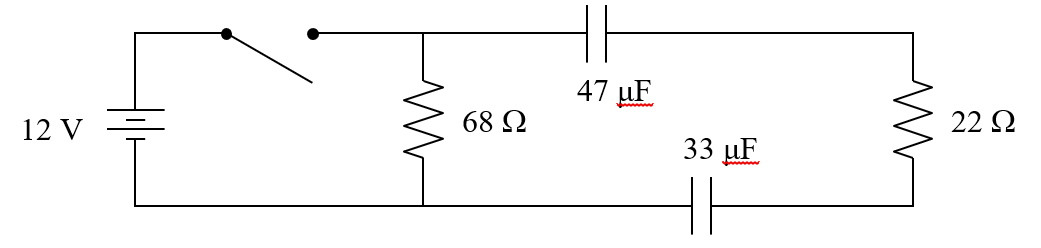
24. Examine the
circuit below in which the two capacitors are initially uncharged. (a) Find
the initial current through the battery at the instant the switch is closed.
(b) After the switch has been closed for a long time what is the charge on each
capacitor? (c) What will be the initial current if the switch is then opened?
(d) Make a careful sketch of voltage vs. time for the 33 μF capacitor
illustrating the described actions.